Table of Contents
Introduction
A High-Power Combiner Assembly is a critical component in microwave & RF systems that allows multiple High-Power RF signals to combine efficiently into a single, High-Power output. These assemblies are categorized in terms of isolated and non-isolated systems. In general, for an isolated Power Combiner, Circulators or Magic-Tees are used. These assemblies are essential in various applications, including telecommunications, military radar systems, and academic scientific research. In this whitepaper we will focus on two newly developed Double-Ridge Waveguide High-Power 2-way RF Combiner Assemblies. The first one is a WRD250 Isolated 2-way Combiner operating from 2.5-7.5 GHz, capable of handling an output average power of 1.5 KW. The second Combiner, wideband WRD500 High-Power RF Combiner Assembly, operates from 6-18 GHz.
Applications
- Power Combining Networks.
- High-Power military & commercial radar systems.
- Satellite applications.
- Solid-state High-Power amplifiers.
Required components to build the RF Combiner Assembly
- 4-port Magic-Tees.
- Right-Angle Adapters.
- High-Power Terminations.
- Dual Broadwall Couplers.
- 90º Machined E-Bend waveguide.
- 90º Machined H-Bend waveguide.
- Waveguide Transitions with Bulkheads.
Designing a High-Power Waveguide RF Combiner Assembly needs special considerations of some critical parameters to ensure a feasible and safe operation. Some of the critical parameters that must be considered are given below:
- RF Sources: The RF Combiner Assembly can have multiple signals from multiple RF sources, such as power amplifiers, transmitters, and antennas. The input signal is combined to get an overall High-Power output.
- Power Handling: High-Power Combiners are designed to handle significant RF power levels. Components and materials must be selected accordingly to prevent damage and ensure safety. Power-handling analysis must be properly conducted using Electromagnetic (EM) simulations to verify the power breakdown for both corona and multi-paction.
- Impedance Matching: Impedance matching is a critical parameter to get an acceptable matching level. In most cases, both the input and output require exceptional matching levels for the overall RF Combiner Assembly. It is essential to minimize the reflected power and to maximize the power transfer of the RF Power Combiner Assembly. Multiple matching techniques are used based on the guiding structure. For the waveguide assembly, multi-section stepped transformers are mostly used for impedance matching.
- Pressurization: In some cases, RF Combiners are required to work under high pressure, especially for satellites and space applications. In general, pressurization is a technique to protect assembly components inside the Combiner from environmental factors such as moisture. Some of the Combiner Assembly operates under high pressure from 15-60 psi.
- Component-by-Component Design: RF Power Combiner Assembly requires multiple components such as Magic-Tees, Couplers, High-Power terminations, adapters, E-bends, and H-bends. Every single component must be designed and tested separately to ensure a better performance. This will ensure ease in the fabrication and the overall optimization process. Upon having all components within the required specifications, we can start the integration process to build the RF Combiner Assembly.
- Integrating the Combining Network: Construct the Combining Network by connecting the components according to your design. One must pay close attention to the layout to minimize signal interference and maintain high signal integrity.
- Testing and Tuning: The fabricated RF Combiner module will be measured using vector network analyzers (VNA) and spectrum analyzers. Ensure that the design meets the required performance specifications, such as insertion loss, isolation, and output return loss. If the required specifications are not met, further tuning may be required to adjust the required specifications as needed to optimize its performance.
- Quality Assessment: To ensure that the design parameters are well aligned with the fabricated unit, it is a good practice to verify the component dimensions based on the gauge meter. For instance, for a Coupler design the wall thickness of a broad wall Coupler has a direct impact on the coupling level, if the exact wall thickness is not maintained the expected coupling level can be never achieved. In addition, the wire dimension for the Coupler or the adapter pill height can play a significant role in the matching level.
- Cooling & Thermal Management and Environmental Considerations: If the RF Combiner is operating at High-Power levels, consider implementing cooling solutions to dissipate heat effectively and prevent overheating. Generally, for High-Power applications, heating fins are used. In addition, the operating environment and any environmental factors that may affect the RF Combiner’s performance, must be clearly understood: temperature; humidity; exposure to the elements.
- Size & Weight Balancing: The physical size and form factor of the RF Combiner Assembly should be appropriate for the intended application, considering space constraints and integration requirements. The overall Combiner is relatively heavy, so the weight of the assembly components must be considered, and the proper weight balancing must be ensured based on the available space frame provided by the customer. Appropriate support/mounting brackets and holes can be provided accordingly.
2-way WRD250 High-Power RF Combiner Assembly
High-Power Combining Assemblies have great significance in radar systems. Shown in Fig. 1, is the block diagram of a 2-way Isolated High-Power RF Combining Assembly. A 2-way isolated Power Combiner Assembly features two input ports, each connected to a separate RF or microwave signal source. These input ports are typically designed for specific frequency bands and power levels. The overall RF Combiner Assembly consists of several components such as WRD250 four-port Magic-Tees, WRD250-7/16(f) Right-Angle Adapter, WRD250 90º Machined EBend waveguide, WRD250 High-Power Termination, WRD250 Dual Broadwall Coupler. For the design and validation, a 2-way Combiner module, and the WRD250 waveguide dimensions were considered which could handle High-Power operating from 2.5-7.5 GHz. The WRD250 Combiner efficiently combines power from two RF sources using a Magic-Tee that governs the phase and amplitude of incoming signals, allowing for smooth and interference-free signal merging. The sum port of the Magic-Tee is terminated by a High-Power WRD250 termination beyond 20 dB matching to protect the RF source. The difference port of the Magic-Tee is integrated with a 30-dB Coupler in the RF Combiner Assembly can either sample input signals or monitor output power, facilitating precise adjustments as required by various applications.

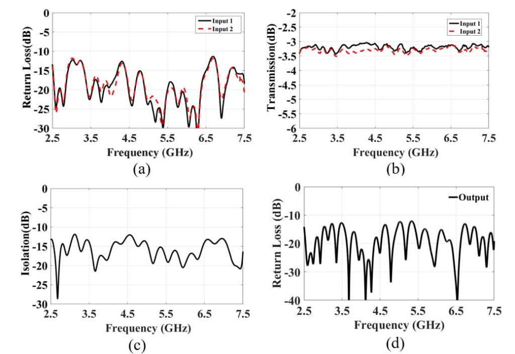
Shown in Fig. 2, are the highlights of the 3D model of the overall WRD600 RF Combiner Assembly. The objective matching level is beyond 12 dB at the output port with a signal transmission of -3 ± 0.5 dB. The input isolation exceeds 12.5 dB matching. The interface of the assembly is a 7/16(f) coaxial connector, which can handle an average power of 420 W CW. All the required components for the RF Combiner module comply with the standard specifications, where each component was tested individually before the final assembly. The WRD250 Coupler’s output interface which is connected to the Magic-Tee has a deferred alignment of 0.75” with the Magic-Tee difference port. From the design perspective, designing the Coupler with bending can be challenging, as it requires multiple optimization processes to obtain the desired coupling level. The WRD250 broad wall Coupler was asymmetric, which took more time in the global optimization process. Furthermore, just like the electrical specifications, the mechanical aspects are also critical for the system, where we need to ensure mechanical stability for the complete assembly.

Shown in Fig. 3 is the input and output return loss of the WRD250 Combiner. The isolation of the Power Combiner Assembly shows beyond the 12 dB isolation level covering the entire operating range.

2-way WRD500 High-Power RF Combiner Assembly
Here, we discuss another Double-Ridge 2-way RF Combiner Assembly based on standard WRD500 waveguide dimensions covering the frequency range from 6-18 GHz. The WRD500 Power Combining Assembly features a 2-way Combiner seamlessly integrated with a dual Broadwall Coupler, offering efficient power combinations from two RF sources. A 4-port Magic- Tee is used to isolate the Power Combiner while having efficient transmission with exceptional phase and amplitude of the incoming signals. Additionally, right-angle adapters at the input ports simplify transitions to the SMA(m) interface, while a dedicated Bulkhead facilitates connection to the output WRD500 interface as highlighted in Fig. 4. The WRD500 Combiner can handle an average power of 200 W CW while maintaining a safe operating over the entire operating bandwidth. The overall Combiner offers a high matching level with low insertion loss, which is suitable for power amplifying structures or antenna feeding systems.
Isolation between the input ports is a critical feature of the High-Power RF Combiner Assembly, where isolation ensures that the signals from each input port do not interfere with one another. It is necessary to maintain signal quality and prevent unwanted crosstalk. The secondary arms of the Broadwall Coupler were specially designed for this project. For feeding purposes, we have developed a U-shaped secondary arm for both the forward and reverse coupling. It is noticeable from Fig. 4 that both the secondary arm ports are on the top side, which facilitates the cable connection.

The input & output return loss, and the isolation indicates a very good matching level covering the entire operating bandwidth from 6-18 GHz demonstrated in Fig. 5. The objective matching level is beyond 10 dB at the output port, and the input isolation exceeds 11 dB matching. The transmission coefficient of the 2-way Combiner shows great stability with a transmission coefficient of -3 ± 1.1 dB over the entire operating range. We have built several prototypes on 2-way High-Power isolated RF Combiners. The performance evaluation of the two proposed RF Combiners is shown below in Table 1.

We have built several prototypes of the 2-way High-Power isolated RF Combiners with Double-Ridge waveguides type. The WRD250S/WRD600 are SMC specially designed Double-Ridge waveguide structures that cover an extremely wide band of 3:1. We also work with WRD600P which is a specially designed Double-Ridge waveguide capable of handling very High-Power. In future, more examples will be described to indicate the performance and design of the specialized Double-Ridge Combiners.
| Waveguide Size | Frequency (GHz) | VSWR Input | VSWR Output | Transmission | Isolation | Coupling (dB) | Directivity (dB) |
|---|---|---|---|---|---|---|---|
| WRD250 | 2.50-7.50 | 1.8:1 | 1.8:1 | 3±0.5 | 12 | -30±2 | 20 |
| WRD500 | 5.00-18.00 | 1.8:1 | 1.8:1 | 3±1.1 | 11 | -50±2 | 20 |
Conclusion & Future Works
We have discussed two newly developed Double-Ridge waveguide 2-way RF Combiner assemblies suitable for High-Power radar systems operating at two different frequency bands. Several components, of which each is tested individually, are integrated to form the Double- Ridge RF Combiner Assembly. The overall assembly can handle High-Power with a very good matching level in the output port as well as 12 dB isolation covering the entire operating range. 4-Way assemblies are also currently available. A more complicated power assembly, being the 8-way Combiner is currently in development, based on the Double-Ridge waveguides to have a wideband performance.
Message from our Team
Our R & D team is always looking for new product developments with innovative solutions in reduced timeframes. Our production team builds our own CAD designs using electromagnetic (EM) simulators, and we have high-precision CNC milling equipment to fabricate with up to 0.0002”-0.0003” tolerances. We can build metallic parts commonly using aluminum, copper, and brass. We can also work with any specialty metal such as Invar or Aeronautic grade aluminum for example, upon the customer’s request. We have high-quality measurement labs ensuring reliable results. We provide chemical treatments, along with the surface finishing for each product in-house. Electroplating services are readily available through outsourcing. Our quality inspection team is focused on verifying the components at each step to meet the customer’s expectation and trust.
Click here to know more about our Power Combining Networks!


