Table of Contents
Introduction
A Circulator is a three-port device where power can be transferred from one port to another while the third port remains isolated. The Port 1 of a Circulator can be considered as a transmit (TX) port, which directly sends the signal to the coupled port. In general, in the coupled port, an antenna is connected, which receives the signal and sends the signal to the receiver (RX) port. A high isolation is required between TX-RX ports. For an Isolator, the third port is terminated with a matched load. Therefore, in terms of the power transfer, the signal can go from Port 1 to Port 2 (full transmission). However, from Port 2 to Port 1 there will be a complete isolation. Tee-junction and Y-junction circulators/isolators are the most used circulators. In a junction Circulator, a ferrite is placed in the middle of the junction, which can be implemented based on various shapes such as (circular, triangular, or hexagonal-shaped ferrite) for the non-reciprocal behavior of the circulator. High-Power Circulators/Isolators are essential in many applications, including telecommunications, military radar systems, and satellite communications. In today’s whitepaper, we will discuss two newly developed High-Power wideband Double-Ridge waveguide Isolators and Circulators covering two different frequency bands. The first component is a Double-Ridge isolator based on the standard WRD350 waveguide dimensions, operating from the 4-8 GHz range with a 2:1 bandwidth ratio. The second component is a WRD200 Circulator design with coaxial interfaces 7/16 (f) operating from 2-4 GHz.
Applications
- Power Combining Networks.
- High-Power military & commercial radar systems.
- Satellite applications.
- RF Source Protection.
Required Components
- WRD High-Power termination.
- Ferrites.
- Tuning screws.
- External biasing DC magnets.
- Cooling fins.
Designing a High-Power Double-Ridge Waveguide Circulator/Isolator needs special considerations of some critical parameters to ensure a feasible and safe operation. Some of the critical parameters that must be considered are given below:
- Frequency & Waveguide Dimensions: The first step for any Circulator/Isolator design is to know the exact operating frequency of the device. Based on the frequency, the exact waveguide size can be realized to start the design procedure. For the Double-Ridge waveguide, it is required to specify the waveguide dimensions including the width, height, and gaps between the two ridges.
- Ferrite Selection: Based on the operating range of the Circulator/Isolator, the appropriate ferrite magnetization needs to be determined to serve the purpose. Microwave Circulators/Isolators mostly use ferrite materials with specific magnetic properties. For High-Power applications, large linewidth ferrites are required to handle the power level. Additionally, for high-frequency applications, high magnetization saturation is essential to have an excellent return loss, isolation, and insertion loss.
- Power Handling Considerations: High-Power Circulators/Isolators are designed to handle significant RF power levels. Components and materials must be selected accordingly to prevent damage and ensure safety. It is highly recommended to use high-thermal epoxy glue on the ferrite base of the Circulator/Isolator module for High-Power applications. If the required power level of the Circulator/Isolator module is very high, a single junction may not handle the required power level, and a different solution may be required. Power-handling analysis must be properly conducted using Electromagnetic (EM) simulations to verify the power breakdown for both corona and multi-paction.
- Impedance Matching: Impedance matching is a critical parameter to get an acceptable matching level. In most cases, both the input and isolation require exceptional matching levels for the High-Power Circulator/Isolator. It is essential to minimize the reflected power and maximize the power transfer of the Microwave Circulator/Isolator. Multiple matching techniques are used based on the guiding structure. For the waveguide assembly, multi-section stepped transformers are mostly used for impedance matching.
- Pressurization: In some cases, RF Circulators/Isolators are required to work under high pressure, especially for satellites and space applications. In general, pressurization is a technique to protect the components from environmental factors such as moisture. Some Circulators/Isolators operate under high pressure from 15-40 psi. Pressurization alleviates the peak power handling, and it protects the component.
- Testing and Post Fabrication Tuning Process: The fabricated Circulator/ Isolator will be measured using vector network analyzers (VNA) and spectrum analyzers. This ensures that the design meets the required performance specifications, such as insertion loss, isolation, and return loss. If the required specifications are not met, further post fabrication tuning may be required to improve the matching level of the overall Double-Ridge waveguide Circulator/Isolator design.
- Quality Assessment: To ensurethat the simulated design parameters are well aligned with the fabricated unit, as a conscientious and ISO certified company, we verify the component dimensions at each step to get the expected performance.
- Cooling & Thermal Management Considerations: If the component is operating at High-Power levels, consider implementing cooling solutions to dissipate heat effectively and prevent excessive heating. Generally, for High-Power applications, heat fins are used. The operating environment and any environmental factors that may affect the RF device’s performance, must be clearly understood, such as temperature, humidity, and exposure to the elements.
- Size & Weight Balancing: The physical size and form factor of the Circulator/Isolator should be appropriate for the intended application, considering space constraints and integration requirements. If the overall module is relatively heavy, proper weight balancing must be ensured based on the available space frame provided by the customer. Appropriate support/mounting brackets and holes can be provided accordingly.
WRD350 High-Power Isolator Design
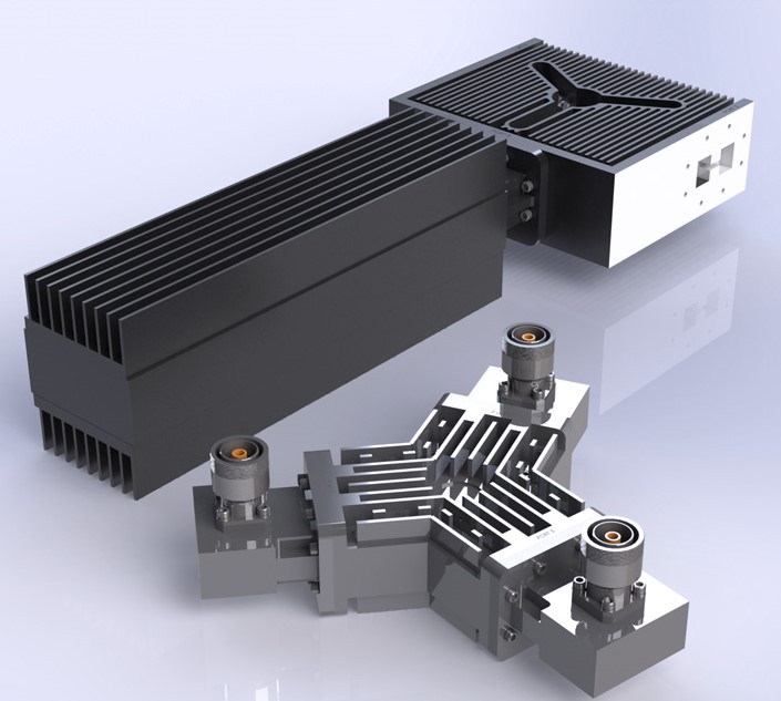
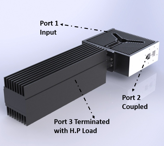
High-Power Isolators are essential components in the RF front end having great significance in satellites and radar systems. Fig. 1 demonstrates the 3D view of a WRD350 High-Power Isolator. It is evident from the figure that all the power is going from Port 1 to Port 2, while Port 3 is terminated with a High-Power WRD350 load to protect the RF source. The selected ferrite type has a saturation magnetization of 1300(G) with a larger linewidth. Moreover, the large linewidth has an internal immunity to the resonance under High-Power conditions. After selecting the ferrite disc based on the required frequency band, the disc impedance was calculated at the center frequency of the operating bandwidth. Hence, we presented a four-matching transformer design to transfer the signal from the center section to the standard waveguide opening. We added also tuning screws at all transformers to have post fabrication methodology. Samarium cobalt DC magnets were used to externally bias the High-Power WRD350 Isolator. The objective matching level is beyond 17 dB at the input port with 17 dB isolation covering from 4-8 GHz range. The insertion loss of the isolator varies from -0.3 ± 0.1 dB over the entire operating range.
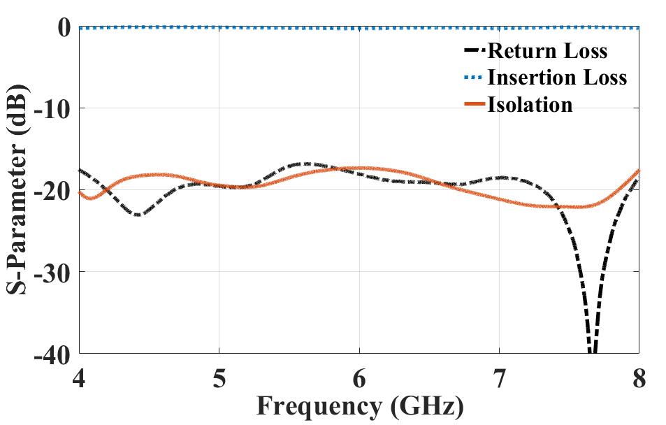
Just like the electrical specifications, the mechanical aspects are also critical for the system, where we need to ensure mechanical stability for the complete assembly. While measuring the isolator, DC magnets were placed from both the top and bottom sides. Tuning screws were also on top of the four matching transformers to increase the return loss and isolation level. A nickel aluminum (C-25) ferrite with a saturation magnetization of 1230(G) and a large linewidth of 390(Oe) is used for the Isolator design. It is worth mentioning, that the broader linewidth is required for High-Power applications.
WRD200 Double Ridge Waveguide High-Power Circulator with Coaxial Interface
The second component for today’s whitepaper is a WRD200 High-Power Coaxial Circulator operating from 2-4 GHz capable of handling an average power of 500W (CW). All three ports of the Circulator have a 7/16(f) coaxial interface handling High-Power. Fig. 3 shows the 3D view of a WRD200 High-Power circulator with a 7/16(f) coaxial interface.
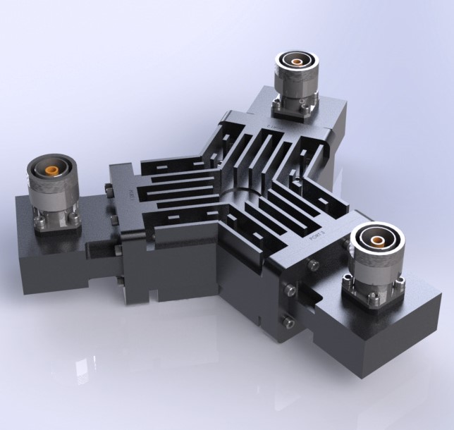
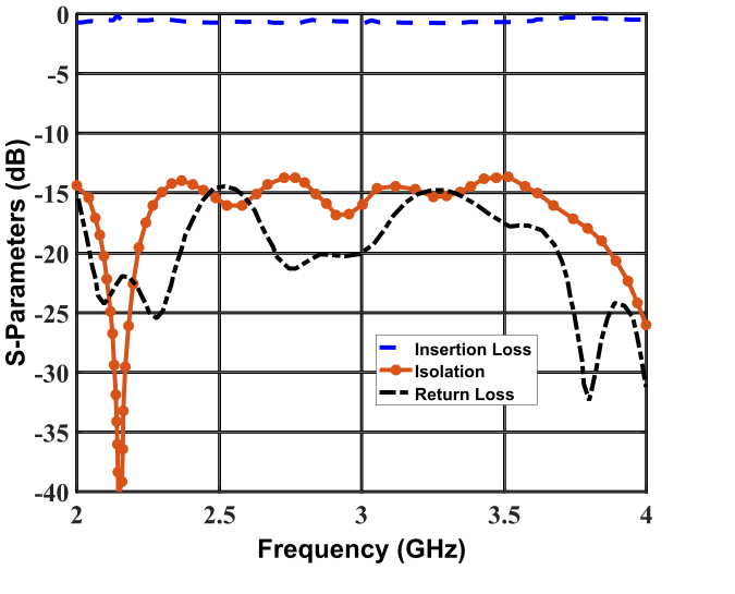
The objective matching level is beyond 14 dB at the input port with 13.5 dB isolation covering from 2-4 GHz range. The insertion loss of the circulator varies from -0.7 ± 0.2 dB over the entire operating range as demonstrated in Fig. 4. It is worth mentioning that the insertion loss as well as the isolation and return loss can be significantly improved if the waveguide interface was considered rather than the coaxial interface. Furthermore, just like the electrical specifications, the mechanical aspects are also critical for the system, where we need to ensure mechanical stability for the complete assembly. While measuring the Circulator, DC magnets were placed from both the top and bottom sides just like the previous WRD350 Double-Ridge waveguide Isolator. Tuning screws were added to improve the return loss and isolation level.
We have built several prototypes of the High-Power Circulator/Isolator supporting various applications. The WRD250S/WRD600 are SMC specially designed Double-Ridge waveguide structures that cover an extremely wide band of 3:1. We also work with WRD600P which is a specially designed Double-Ridge waveguide capable of handling very High-Power. In future, more examples will be described to indicate the performance and design of the specialized Double-Ridge High-Power circulators/isolators. The performance evaluation of the two proposed Circulator and Isolator is shown below in Table 1.
| Waveguide Size | Frequency (GHz) | Interface | VSWR | Insertion Loss (dB) | Isolation (dB) |
|---|---|---|---|---|---|
| WRD350 | 4.00-8.00 | Waveguide | 1.35:1 | 0.3±0.1 | 17.5 |
| WRD200 | 2.00-4.00 | Coaxial 7/16(f) | 1.6:1 | 0.7±0.2 | 13.5 |
Conclusion & Future Works
for High-Power radar systems operating at two different frequency bands. We have demonstrated both the waveguide and coaxial interfaces to build our components. These High-Power components can be integrated with power combiners for radar systems. Both components can handle High-Power with an exceptional matching level. A more complicated Isolator design is currently in development with dual junctions based on the Double-Ridge waveguides to handle more power.
Message from our Team
Our R & D team is always looking for new product developments with innovative solutions in reduced timeframes. Our production team builds our own CAD designs using electromagnetic (EM) simulators, and we have high-precision CNC milling equipment to fabricate with up to 0.0002”-0.0003” tolerances. We can build metallic parts commonly using aluminum, copper, and brass. We can also work with any specialty metal such as Invar or Aeronautic grade aluminum for example, upon the customer’s request. We have high-quality measurement labs ensuring reliable results. We provide chemical treatments, along with the surface finishing for each product in-house. Electroplating services are readily available through outsourcing. Our quality inspection team is focused on verifying the components at each step to meet the customer’s expectation and trust.
Click here to know more about our Double-Ridge Circulator/Isolator!
